Description
How to Specify Expanded Aluminum Mesh in Architectural Drawings
The Drawing Details That Prevent Wrong Mesh Patterns, Fabrication Errors and Costly Facade Rework
Two expanded aluminum mesh panels can have exactly the same overall dimensions, material thickness and diamond-shaped openings, yet look completely different after installation.
Why?
Because one drawing may specify only the mesh size, while another identifies the strand direction, visible face, opening geometry and panel orientation.
For architectural facade projects, these small details can determine whether hundreds of square meters of expanded metal mesh match the architect’s original design.
A note such as “3 mm aluminum expanded mesh, diamond pattern, powder coated” might be enough for a preliminary discussion. It is rarely sufficient for fabrication.
So, how should architects specify expanded aluminum mesh in construction drawings to avoid misunderstandings between designers, manufacturers and facade contractors?
Let’s examine the details that matter most in actual projects.
1. Why Is Expanded Aluminum Mesh More Difficult to Specify Than a Solid Aluminum Panel?
A solid aluminum panel is relatively straightforward to describe. Architects generally identify its length, width, thickness, alloy, finish and fixing arrangement.
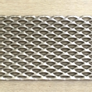
Expanded aluminum mesh requires additional information because its openings are created by slitting and stretching a metal sheet.
The resulting geometry includes several interconnected dimensions.
Changing one dimension can affect the opening size, transparency, material consumption, structural behavior and visual appearance.
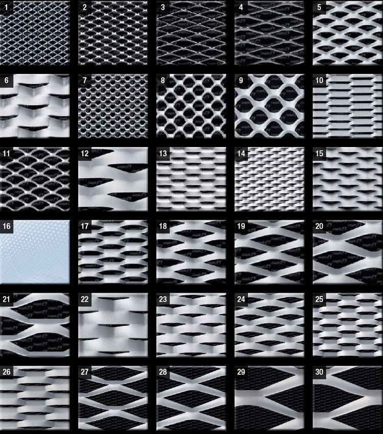
For example, consider two expanded mesh products:
| Parameter | Mesh A | Mesh B |
|---|---|---|
| Original sheet thickness | 3.0 mm | 3.0 mm |
| SWD | 60 mm | 60 mm |
| LWD | 150 mm | 150 mm |
| Strand width | 5 mm | 8 mm |
| Visual appearance | More open | Denser |
| Approximate material coverage | Lower | Higher |
These are illustrative geometries, not verified stock products. Actual open area must be calculated from the manufacturer’s final mesh geometry.
Even though both meshes share the same SWD, LWD and material thickness, the difference in strand width can noticeably change the facade.
This is why simply writing “expanded aluminum mesh 150 × 60 × 3 mm” can lead to confusion.
2. What Do SWD and LWD Mean on Expanded Aluminum Mesh Drawings?
Two of the most important dimensions in expanded aluminum mesh specifications are:
-
SWD — Short Way of Diamond
-
LWD — Long Way of Diamond
These describe the short and long directions of the diamond-shaped mesh pattern.
However, one important detail is frequently overlooked: SWD and LWD are generally defined as nominal center-to-center pitches of the mesh pattern, not necessarily the clear opening dimensions.
Example: Expanded aluminum mesh 150 × 60 mm
A typical preliminary specification may state:
| Drawing item | Value |
|---|---|
| LWD | 150 mm |
| SWD | 60 mm |
| Original sheet thickness | 2.5 mm |
| Strand width | 6 mm |
| Mesh type | Raised expanded aluminum mesh |
| Material | Aluminum alloy 3003-H14, subject to availability |
This information describes the basic mesh geometry, but it still does not define the complete finished facade panel.
The architect must also identify which diamond direction runs horizontally or vertically across the building.
Drawing tip: Always indicate the SWD and LWD measurement directions with dimension arrows, using the manufacturer’s confirmed definitions. If the project requires a specific clear opening, show that dimension separately.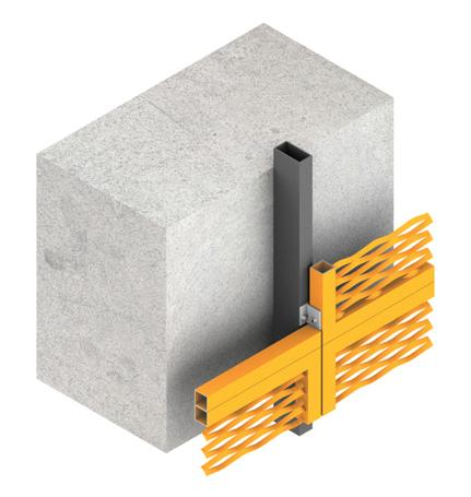
3. Never Confuse Strand Width With Material Thickness
One of the most common specification mistakes is treating strand width and sheet thickness as the same dimension.
They are different.
Material thickness (T) refers to the thickness of the aluminum sheet before expansion, unless the specification explicitly defines another measurement condition.
Strand width (W) refers to the width of the remaining metal strip between openings, measured according to the manufacturer’s mesh geometry.
For example:
-
Sheet thickness: 2.5 mm
-
Strand width: 6 mm
These values influence different aspects of the product.
Sheet thickness contributes to material stiffness and fabrication characteristics, while strand width affects the opening geometry, weight and visual density.
Neither parameter alone is sufficient to determine the load capacity of a finished mesh panel.
For raised expanded mesh, the overall mesh depth may also differ from the original sheet thickness. Therefore, the drawing should distinguish between original material thickness and finished mesh overall depth when relevant.
4. Should the Mesh Direction Be Shown on Architectural Elevations?
Absolutely.
Imagine a facade containing 300 expanded aluminum mesh panels.
The architect wants the long diamond direction to run vertically.
However, the fabrication drawing identifies the panel dimensions without indicating mesh orientation.
During production, some panels are cut with the long diamond direction horizontal, while others are cut vertically.
The result is an inconsistent facade appearance, even though the individual mesh sheets meet their nominal dimensional specifications.
How to specify the mesh direction
Include a clear note on the architectural elevation or shop drawing:
LWD direction shall run vertically. Maintain consistent mesh orientation and visible face across all facade panels unless otherwise indicated.
The drawing should also include a directional arrow and identify the intended exterior-facing surface.
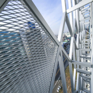
This is especially important for raised expanded aluminum mesh because its angled strands can create directional shading and visibility effects.
Rotating or reversing a panel may change the way it reflects sunlight.
For large facade projects, the manufacturer should confirm the mesh direction before cutting and framing.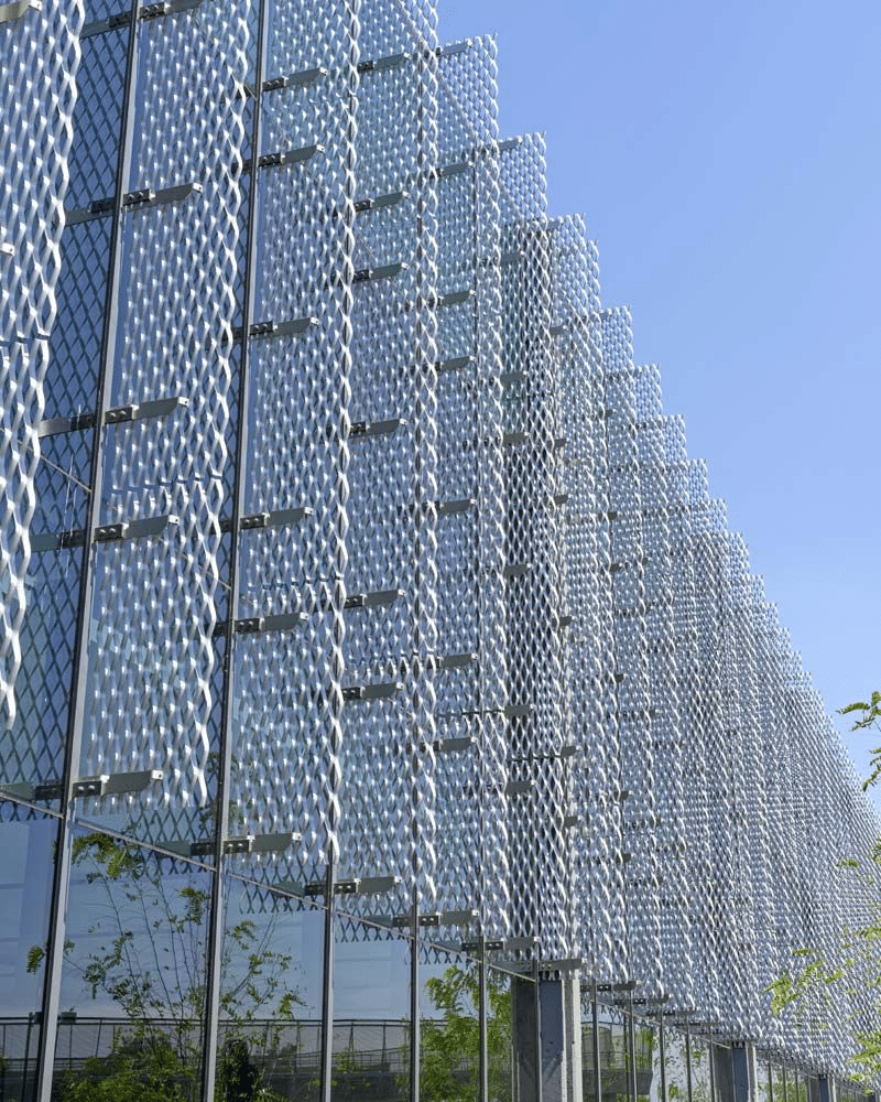
5. How Should Panel Dimensions Be Specified?
A common source of confusion is whether the stated dimensions refer to the expanded mesh sheet itself or the complete framed panel.
Consider a drawing labeled:
Expanded Mesh Panel: 1200 × 3000 mm
Does this refer to:
-
The overall outside dimensions of the finished panel?
-
The dimensions of the mesh sheet before framing?
-
The visible opening between the frame members?
-
The clear architectural module between adjacent panels?
These dimensions may differ significantly.
Recommended drawing approach
| Drawing dimension | What it should identify |
|---|---|
| Overall panel width | Outside-to-outside finished panel dimension |
| Overall panel height | Outside-to-outside finished panel dimension |
| Mesh cut size | Actual sheet dimensions before assembly |
| Visible mesh area | Exposed patterned area after framing |
| Frame dimensions | Width, depth and wall thickness of framing profiles |
| Panel joint | Designed clearance between adjacent units |
| Fixing locations | Position of brackets, holes and fasteners |
If a 1200 × 3000 mm panel includes a surrounding frame, the mesh cut size may need to be smaller or larger than the visible opening, depending on the connection design.
The architect should therefore distinguish architectural module dimensions from manufacturing dimensions.
Practical recommendation: For large projects, use a panel schedule assigning each panel type a unique identification number, such as EM-01, EM-02 and EM-03.
This makes production, packing and site installation easier to coordinate.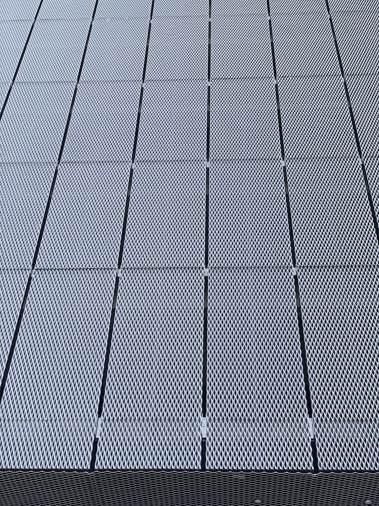
6. How Should Open Area Be Specified?
The open area percentage indicates how much of the mesh’s projected surface is open.
It is relevant to facade transparency, airflow, daylight transmission and solar shading.
However, the relationship between open area and performance is not always straightforward.
For example, a mesh with 50% projected open area does not necessarily transmit 50% of direct sunlight at every solar angle.
The strand geometry and viewing direction influence the actual result.
What should be included in the drawing?
Rather than specifying only “50% open area,” architects should consider including:
-
Required nominal projected open area.
-
SWD and LWD dimensions.
-
Strand width and original sheet thickness.
-
Raised or flattened mesh construction.
-
Direction of installation.
-
Acceptable dimensional and open-area tolerances.
The open area should be verified using the manufacturer’s agreed calculation or measurement method.
For shading-sensitive buildings, a physical mock-up or solar simulation may be required to confirm the intended performance.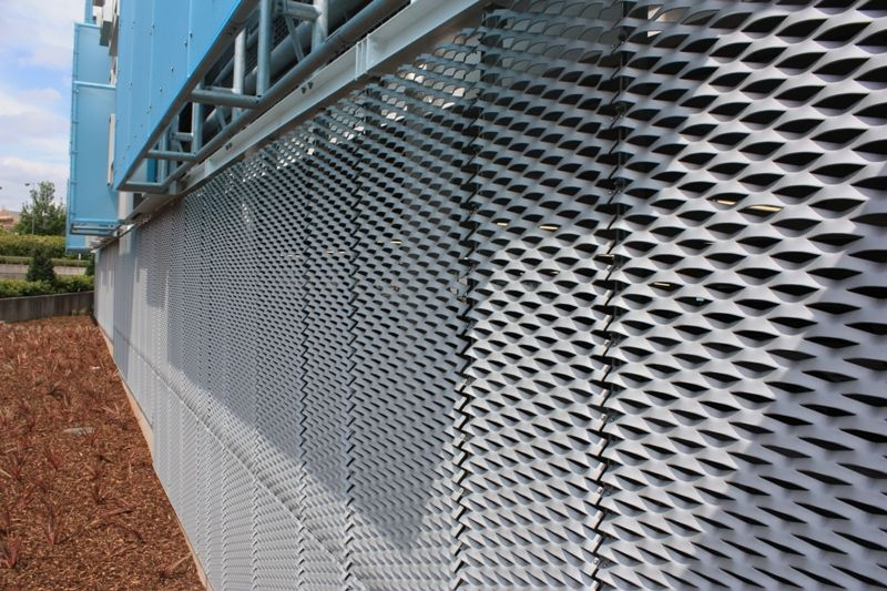
7. Raised or Flattened Expanded Mesh: Why the Drawing Must Say Which
Both types may have similar diamond-shaped patterns, but their surface geometry and visual effects differ.
Raised expanded aluminum mesh is often considered for architectural screens where directional texture and shadow are part of the design.
Flattened expanded mesh may be preferred when a flatter surface or different fabrication characteristics are required.
However, flattening can alter the mesh’s dimensions and material properties.
Therefore, architects should not assume that raised and flattened expanded mesh with nominally similar opening dimensions are interchangeable.
A complete drawing should identify the required mesh type and relevant finished dimensions.
8. How to Specify Aluminum Alloy and Surface Finish
Architectural drawings sometimes state only:
“Aluminum expanded mesh with powder coating.”
This description leaves several questions unanswered.
Which aluminum alloy should be used? What is the required finish color? Is the coating intended for interior or exterior exposure? How will the coating be inspected?
Material specification
Commonly considered aluminum alloys include:
| Aluminum alloy | Typical consideration |
|---|---|
| 1100 | Formability and decorative applications |
| 3003 | Architectural applications requiring good formability and corrosion resistance |
| 5052 | Higher-strength applications where suitable forming and expansion processes are available |
The final alloy and temper must be selected based on the required geometry, fabrication process, structural design and manufacturer capability.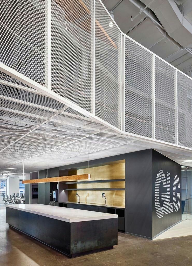
Surface treatment specification
For outdoor architectural mesh, common finishing options include polyester powder coating and suitable PVDF coating systems.
The drawing should identify:
Color: RAL code or approved physical color sample.
Finish: Matte, satin, gloss or another specified appearance.
Coating system: Powder coating or a defined PVDF system.
Performance requirements: Applicable project coating standard, pretreatment, film thickness, adhesion, weathering and corrosion-resistance criteria.
Approval procedure: Color sample or production mock-up approved before mass finishing.
For expanded mesh, the coating must adequately cover the strands and cut edges. The project specification should also account for coating buildup around openings and connections.
9. How Should Fixing Details Be Shown?
A mesh panel cannot be installed safely simply because its overall dimensions are correct.
The connection between the mesh, surrounding frame and building structure must be properly designed.
Common fixing arrangements include mechanically fastened mesh panels, framed panels and engineered clamping systems.
Depending on the project, welding may also be used for suitable metal components, subject to material compatibility and approved fabrication procedures.
Important drawing information
The detail drawings should identify:
-
Mesh-to-frame connection method.
-
Frame profile size and material.
-
Bracket geometry and material.
-
Fastener type, diameter, grade and quantity.
-
Anchor locations and substrate requirements.
-
Allowances for thermal expansion.
-
Corrosion protection between dissimilar metals.
-
Installation and replacement access.
Where the mesh is part of a facade system, the supporting structure and fixing connections must be verified against the applicable project loads.
A manufacturer can produce components according to approved drawings, but structural adequacy must be established by the responsible qualified design professionals.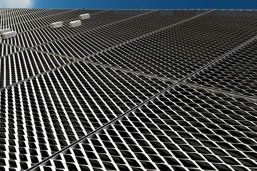
10. Example: Expanded Aluminum Mesh Specification for an Architectural Drawing
Below is an illustrative specification that architects and contractors can adapt when preparing facade drawings or requesting manufacturer quotations.
Sample Drawing Specification — EM-01
Copy specification
| Panel type | EM-01 |
| Product | Raised expanded aluminum mesh panel |
| Material | 3003-H14 aluminum, subject to confirmation |
| LWD | 150 mm |
| SWD | 60 mm |
| Sheet thickness | 2.5 mm |
| Strand width | 6 mm |
| Mesh orientation | LWD vertical |
| Overall panel size | 1200 × 3000 mm including frame |
| Finish | Exterior powder coating, RAL 7016, matte |
| Fixing | Mechanically fixed, engineered connections |
| Open area | Manufacturer to confirm |
Example only. All dimensions, alloy availability, tolerances, structural requirements and fabrication details must be confirmed before production.
This format provides a clearer starting point for shop drawing development than a short material description.
For complex facade projects, a separate detail sheet should show the panel section, framing system, mesh direction, support brackets and installation joints.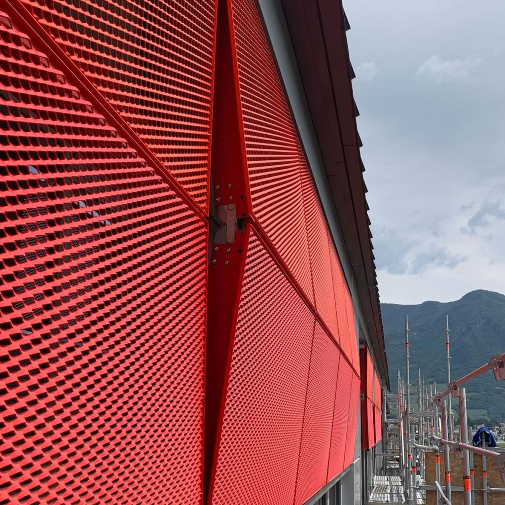
11. Five Drawing Mistakes That Can Delay Expanded Mesh Production
Even experienced project teams occasionally overlook important mesh details.
| Drawing mistake | Possible result |
|---|---|
| SWD and LWD are not clearly identified | Wrong opening geometry |
| Mesh direction is not shown | Inconsistent facade appearance |
| Overall dimensions are confused with mesh cut sizes | Panels do not fit the intended modules |
| Raised or flattened mesh is not specified | Unexpected surface profile |
| Fixing and frame details are incomplete | Fabrication delays and installation changes |
Another frequently overlooked issue is the position of cut diamonds along the panel edges.
Two panels with identical outside dimensions may have different-looking borders if the diamond pattern is not positioned consistently.
For highly visible architectural facades, the designer should consider defining the starting position of the mesh pattern and acceptable edge conditions.
This is particularly important where several mesh panels are installed side by side and the architect expects a continuous visual pattern.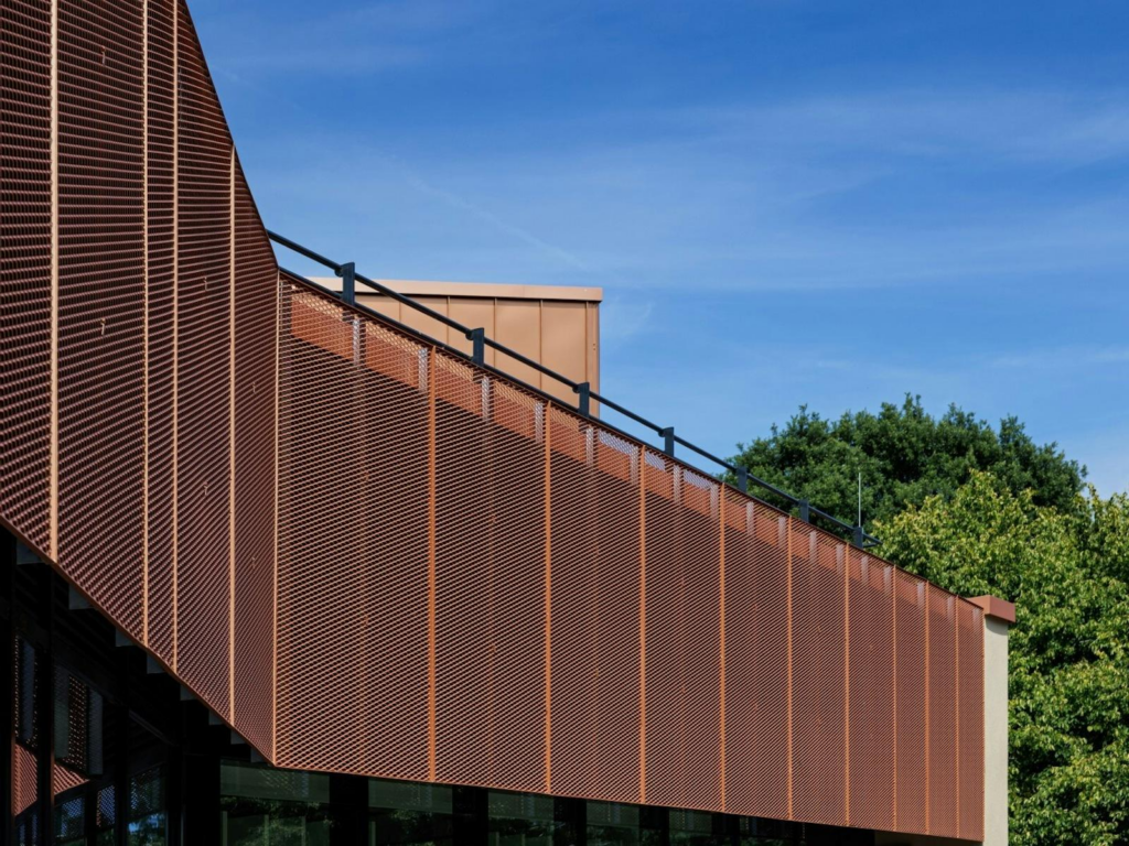
12. Should Architects Request a Mesh Sample Before Approving Shop Drawings?
Yes, especially for large exterior facade projects.
A small material sample can confirm the basic mesh pattern, alloy appearance and coating color.
However, a small sample may not reveal every issue associated with the finished panel.
For projects involving complex geometry, large modules or highly visible facades, a full-size mock-up may be more useful.
It allows the project team to evaluate:
-
Mesh orientation and visual transparency.
-
Edge cutting and pattern alignment.
-
Frame appearance and joint dimensions.
-
Fixing details and installation tolerances.
-
Surface coating consistency.
-
Appearance under different viewing angles and lighting conditions.
Approving a representative sample before mass production can help reduce disagreements over visual quality.
The approved sample should be referenced in the production documentation, together with measurable acceptance criteria.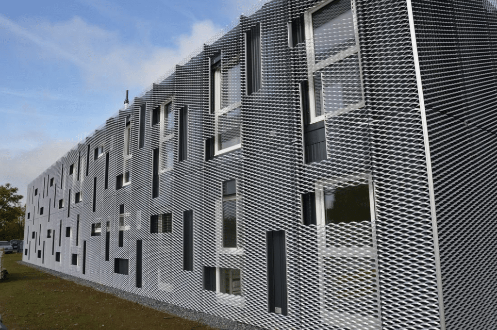
13. Expanded Aluminum Mesh Manufacturing Support From Foshan Qi Aluminum
At Foshan Qi Aluminum Decorative Materials Co., Ltd., we manufacture expanded aluminum mesh and other architectural metal products for facade and interior decoration projects.
We understand that architectural drawings often contain design intentions that require additional clarification before production.
Our team can assist customers with reviewing mesh specifications for manufacturability, discussing available patterns, preparing fabrication information and producing samples for approval.
Our manufacturing services include expanded aluminum mesh panels, aluminum framing components, powder coating, PVDF finishing options and export packaging.
For architects, contractors and purchasing managers, providing complete drawings helps us prepare more accurate quotations and reduce unnecessary revisions during production.
Have an expanded aluminum mesh drawing that needs a manufacturing quotation?
Send us your CAD or PDF drawings, mesh specifications and estimated project quantities.
We can help review the manufacturing details and discuss suitable production options.
Company: Foshan Qi Aluminum Decorative Materials Co., Ltd.
Website: www.aluminum-panel.com
Email: [email protected]
WhatsApp: +86 13542961174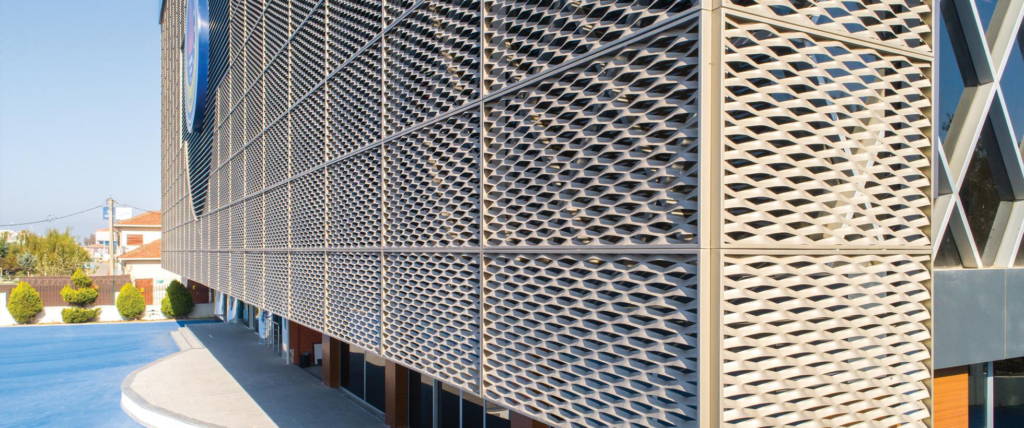
Frequently Asked Questions
What does 150 × 60 × 2.5 mm mean for expanded aluminum mesh?
It commonly refers to nominal LWD of 150 mm, SWD of 60 mm and original sheet thickness of 2.5 mm. However, the drawing should explicitly identify the order and meaning of these dimensions. Strand width, mesh type and orientation must also be specified.
Is SWD the same as the clear opening width?
Not necessarily. SWD generally refers to the nominal short-way pitch of the diamond pattern. The clear opening depends on strand geometry and the measurement method. Always confirm the manufacturer’s dimensional definitions.
Should expanded aluminum mesh be shown in section drawings?
Yes. Section drawings help identify the finished mesh profile, supporting frame, fixing method, cavity dimensions and relationship to the main building structure.
Can expanded aluminum mesh panels be manufactured directly from architectural elevations?
Architectural elevations provide important design information, but detailed fabrication drawings are usually needed before production. These should confirm mesh geometry, panel dimensions, framing, connections, orientation and applicable tolerances.
What drawing files should be sent to the manufacturer?
DWG, DXF and PDF files are commonly useful. For complex three-dimensional panels, suitable 3D models may also help clarify geometry. The manufacturer should confirm the supported file formats and required level of detail.
Conclusion: A Good Expanded Aluminum Mesh Drawing Eliminates Guesswork
Expanded aluminum mesh is not difficult to manufacture when its requirements are clearly defined.
The real challenge is translating an architectural design into measurable and repeatable fabrication instructions.
A complete specification should explain more than the material thickness and diamond size. It should establish the mesh geometry, strand direction, visible face, panel dimensions, edge conditions, framing, connections and surface finish.
For large facade projects, these details can make the difference between a smooth installation and costly rework.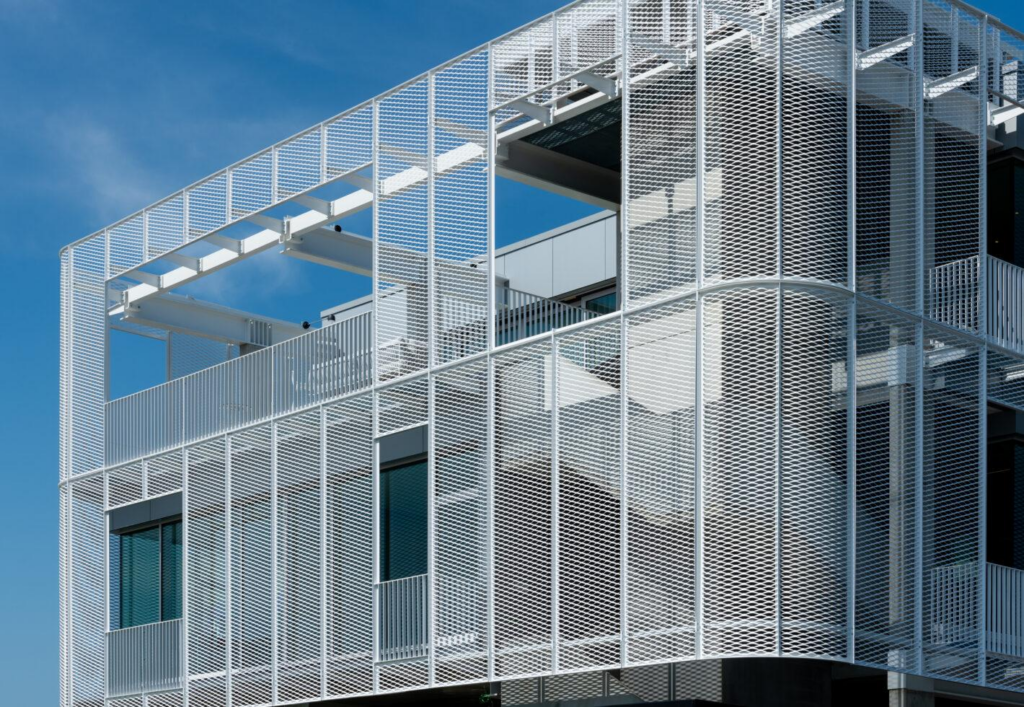
About us:
Foshan Qi Aluminum Decorative Materials Co.,Ltd, more than 12 years experience. We are manufacturer of fabricating aluminum perforated sheets, aluminum solid panels, aluminum screen,aluminum facade decorative sheets, aluminum expanded mesh, aluminum ceiling with good quality and fast delivery for more than 10 years to export countries. Our monthly supplying is about 80000 sqms for inside and outside market. Our projects covers five star hotel, high end villas, school, campus, metro station, airport, office building, shopping mall and some other goverment projects. We can provide design, fabrication and installation one stop service for your projects. High precision, quality guarantee, affordable price, globla delivery and considerate service is our basis. We accept OEM/ODM business. We are the experienced specialist on facade solution decoration!!!